Pipework
PIPEWORK SYSTEMS
Neobros Ventures Corporation is certified by Franklin Fueling System for UPP pipe installation here in the Philippines. UPP systems are also used for government and military installations as well as many industrial sites such as mines and rail depots.
UPP pipework is a lightweight, flexible, non-metallic, above & below ground pipework system for oils, fuels & spirits, using the latest co-extrusion technology. UPP piping systems are designed in various diameters, from 32-160mm (I”-6”) for the transfer of fuels in filling station fore courts, marinas, and airports.
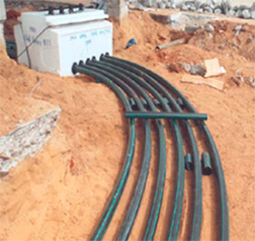
CONTINUOUS INSTALLATION
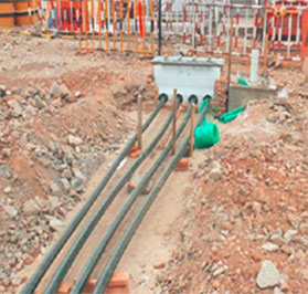
JOINTED INSTALLATION
Type of UPP Installation
UPP Systems must only be installed by fully trained and certified installers. It is important, to any type of piping system, for all metallic components be safely connected to the ground. Metallic components, and more general conductive materials, due to their high capacitance, can have the potential to store high amount of electrostatic energy (sparks discharge can only be observed over conductive elements).
All exposed metal parts used in UPP System installations should be adequately grounded to a dedicated earth electrode and brought to a potential equal to that of other metal parts in the close proximity.
UPP pipework systems has two type of UPP installation: Continuous Installation and Jointed Installation. The piping system shall be installed as specified on contract drawings or at the discretion of the installing contractor to provide a complete pipe conveyance system as required for the project. Pipe sizes shall be as shown on the contract drawings. All pipe and fittings installed or constructed in the field shall be assembled and fusion-welded by employees of the contractor who have been trained and certified by the manufacturer. The piping system shall be installed in strict accordance with the manufacturers current installation published installation instructions.
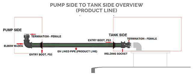
PIPE INSTALLATION OVERVIEW
The piping system shall be installed as specified on contract drawings or at the discretion of the installing contractor to provide a complete pipe conveyance system as required for the project. Failure to follow installation instructions will invalidate warranty and installer certification. Make sure that the Welding Units are connected to the power supply and meets the requirements detailed in the user manual of any local authority or regional legislation.
Here are the following guidelines to ensure a successful installation: First, all pipe must be cut square and scraped to remove the oxidation area before Electrofusion. Second, all Spigot fittings supplied un-bagged must be scraped to remove the oxidation area before electrofusion. Then, all the pipes, fittings, and sockets must be cleaned with acetone where they join. Lastly, the joints should have the pipe inserted into the electrofusion fitting ensuring that the marked insertion depth is reached and must not be under any stress during welding or until ambient temperature is reached after welding.
Tank sumps, transition sumps, and dispenser sumps shall all be made of HDPE and manufactured or otherwise as recommended by Franklin Fueling Systems.
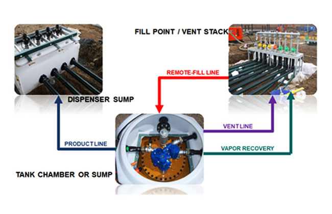
TYPICAL SITE LAY-OUT
It is very important that the site should be free from previous fuel contamination. The area in which the pipe is uncoiled on site must be clear, safe, and free of sharp objects. Organize all necessary tools and equipment on the job site prior to commencing the installation of pipe and fittings.
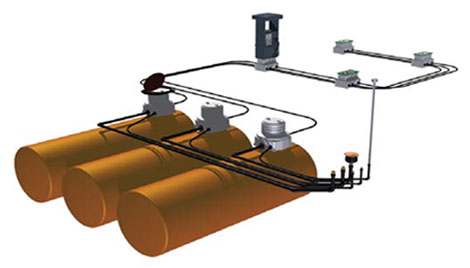
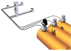
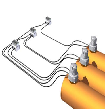
PRESSURE SYSTEM
- Single wall or double wall pipe
- Series pipe lines
- Sumps connected
- Shear valves
- Submersible pump
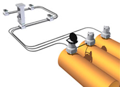
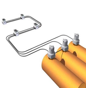
PRESSURE SYSTEM
- Single wall pipe
- Multiple pipe lines
- Angle check valve
- Often no pump sumps
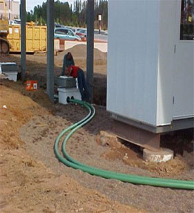
Site Preparation
Make sure the site is prepared and ready. The tanks and sumps should be in place. Pipe Burial Guidelines recommended burial depth of UPP pipe is a minimum of 12" (300mm). All trenches should be sloped back towards the storage tanks. The fall back (slope) for all pipework to the tank chambers should be a minimum of 1/8" per foot or 1m every 100m. This may vary to meet local requirements.
The position of the entry fittings at the furthest dispenser sump away from the tank chambers may be considerably higher than that of the entry fittings on the closest dispenser sump.
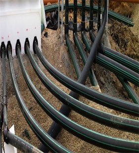
Vapor return lines should have a slope of 1/4" per foot and never less than 1/8" per ft. back towards the tank farm, unless in-line joints such as elbows are to be used and trench corners should have a radius of 5ft (1.5m). A recommended 6" (15cm) bed of backfill material should be laid underneath the pipe prior to installation and there must never be voids under or around the pipe.
Clean washed sand and backfill material must not be contaminated with any petroleum product or other contaminant. When laying duct onto a concrete base a 6" (150mm) thick bed of compacted sand should be laid on the concrete, below the duct.
All beds should be laid so that the pipe will not dip or sag when it is installed. Laying of pipe should start from the tank farm. Underground pipe runs may be continuous or have electrofusion welded joints. Any mechanical joints or compression fittings must be located within a containment chamber or sump.
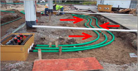
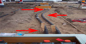
sneaking pipe
temporary stakes